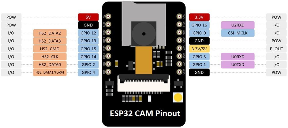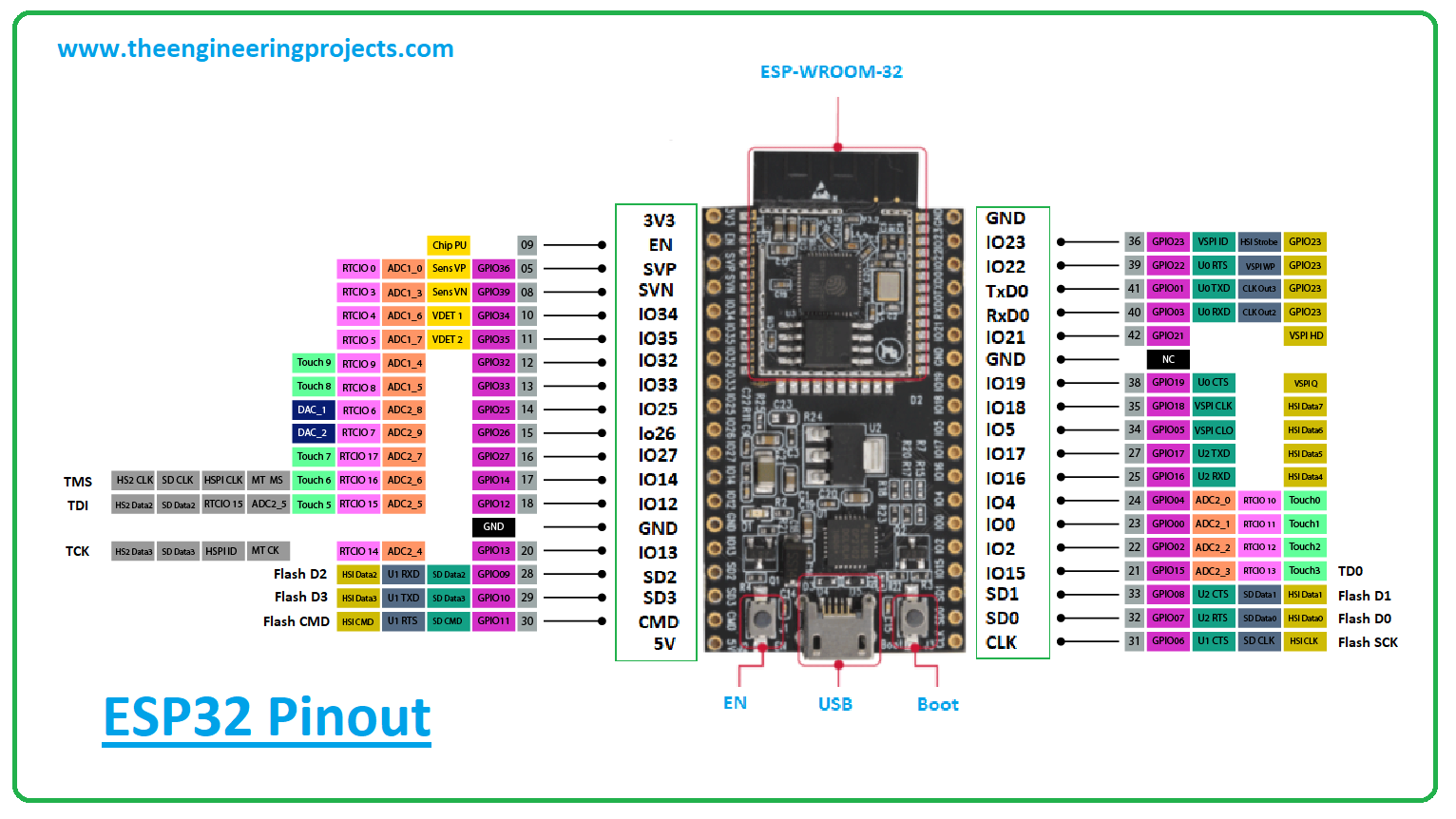
If you’re not using the microSD card, you can use these pins as regular inputs/outputs. The following pins are used to interface with the microSD card when it is on operation. To make the ESP32 run “normally”, you just need to disconnect GPIO 0 from GND.


GPIO 0 determines whether the ESP32 is in flashing mode or not. However, you won’t be able to open the Serial Monitor and see if everything is going well with your setup.

You can use GPIO 1 and GPIO 3 to connect other peripherals like outputs or sensors after uploading the code. Learn how to upload code to the ESP32-CAM AI-Thinker. The best way to upload code to the ESP32-CAM is using an FTDI programmer. Because the ESP32-CAM doesn’t have a built-in programmer, you need to use these pins to communicate with the board and upload code. GPIO 1 and GPIO 3 are the serial pins (TX and RX, respectively). If you want to have an output of 5V on the VCC pin, you need to unsolder that connection and solder the 5V pads. If you aren’t using a microSD card, you can use these pins as regular inputs and outputs.If you look closely, you should have a jumper on the 3.3V pads. The following pins are used for interfacing the microSD card. This LED is internally connected to GPIO 4. It is intended to be used as a camera flash, but it can also be used for general illumination. The ESP32-CAM has a very bright white LED. This LED works with inverted logic, so to turn it on, you send a LOW signal and to turn it off, you send a HIGH signal. It is user-programmable and connected to GPIO33. There is a small red LED on the back that can be used as a status indicator. Remember! You’ll have to make this connection every time you want to upload a new code. Once you have finished programming the board, you must disconnect this connection. When you connect GPIO 0 to GND, the ESP32 enters flash mode, and you can upload code to the board. This GPIO must be HIGH during boot and LOW during flashing, so it is internally pulled up by a 10K resistor. It determines whether or not the ESP32 is in flashing mode.


 0 kommentar(er)
